- Coordinator: Maja Olvegard (University of Uppsala, Sweden)
- Co-coordinator: Elena Wildner (CERN, Switzerland)
- Team members:
- Elian Bouquerel (CNRS, FR)
- Tord Ekelof (Uppsala University, SE)
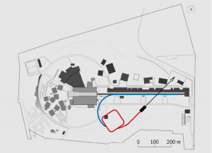
Work package 3 is in charge of designing an accumulator ring that will collect beam pulses from the linac and compress them before they are sent on to the target where the neutrino superbeam is formed. In addition to designing the ring, the work package includes the transfer line that brings the beam from the linac to the accumulator, and the so-called switch yard that takes the beam pulses from the accumulator ring and distributes them over the four target stations.

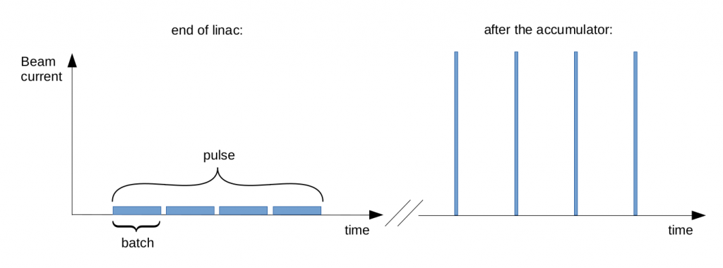
There are several challenging aspects of Work Package 3. One of them is to be able to store the high number of particles that are contained in each beam pulse. The particles in the beam all have the same charge which means that they will repel each other through the Coulomb force. At the same time, since they are moving, there is an attractive magnetic force in the beam. These two effects combined are called space charge and give the net effect of an internal repulsive force which can be strong in low energy, high intensity beams. Space charge can lead to an increase of the beam size, and eventually beam losses, over the many turns that beam circulates. Since the space charge increases with particle density, we have decided to split up each beam pulse from the linac into four batches. These batches will be accumulated one after the other so that the maximum number of particles in the ring is reduced to just over 2.2·1014. In addition, we want to form a beam distribution which is as uniform as possible to further minimize the effects of space charge.

The accumulation will take place through multiturn injection. That means that the beam coming from the linac will be merged with itself as it enters and circulates in the ring. In this way the long pulse from the linac is transformed into a more dense beam pulse, a beam pulse that now has a duration that corresponds to the revolution time in the ring.
The injection takes place through phase space painting. Here, we use a fixed injection point so that the injected beam always arrives at the same spot, at the same angle. Meanwhile, the orbit of the circulating beam is shifting with respect to the injection point. Normally, the orbit starts very close to the injection point, meaning that the first turns end up at the center of the final beam. As the injection continues, the orbit moves further and further away from the injection point. In this way the injected beam “paints” the phase space of the circulating beam, and the beam that is finally extracted from the ring is larger than the beam that was injected. Here, we have the possibility of generating a beam with the desired uniform distribution, by controlling the way that the orbit varies during injection.
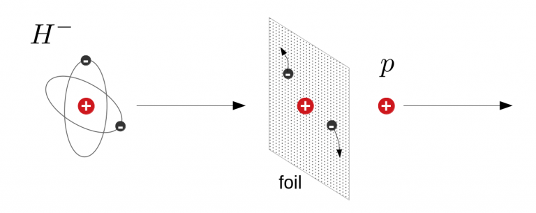
For the injection to happen without too much loss it is likely that the beam being injected, i.e. the one coming from the linac, must consist of H- ions, meaning a proton with two electrons attached to it. This means that the linac must be able to accelerate the H- ions simultaneously with the proton beam that will be used for neutron production. As soon as the H- ions enter the ring they are stripped from their electrons so that the circulating particles become a proton beam. There is a risk that the H- is stripped prematurely when it passes through a magnetic field, for example in the steering magnets in the transfer line from linac to accumulator. This can be avoided by giving the transfer line a large curvature so that the magnetic fields are kept weak. However, the buildings on and the outer perimeter of the ESS site puts an upper limit to the curvature.
The stripping of the H- ions can be done by forcing the beam to pass through a thin foil, but for every beam particle that crosses the foil a small amount of heat is deposited. Since there are many particles in the beam it means that the foil will heat up substantially just after a few batches. If there is no time in between batches for the foil to cool down, it will eventually melt, something that must be avoided. One way is to make sure that the particles only cross the foil when they are to be stripped and not when they are circulating in the ring. Simulations are used to optimize the particle injection in order to ensure this. In the end, we are looking for the golden mean between low space charge in the beam and a minimized number of particle crossings through the foil.

An alternative to foil stripping is laser-assisted stripping, which is being developed and tested in the USA and Japan. In this scheme the ion beam is overlapped with a laser beam. The laser excites the ions so that its electrons are more loosely bound to the proton. Once excited, the ions are passed through a magnetic field, which forces the electrons and the protons to go in opposite directions. Through this the ions are stripped. The results of the tests are promising and the ESSnuSB project is hoping that the technique will be mature by the time of the start of the project. If not, foil stripping will be used. Once a beam pulse has been accumulated it is extracted all at once using very fast magnets. The beam pulse now has a duration of about 1 microsecond. As an alternative we are investigating if we can let the beam “leak” out during a few tenths of microseconds. If so, we would have a slighty longer pulse with a very high intensity that could be sent back to the neutron target. This kind of short neutron pulse is desired by some neutrons users.

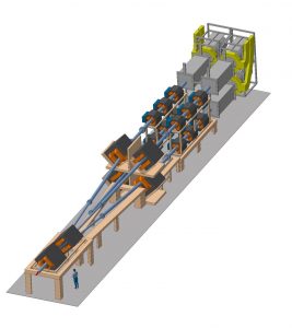
The 1 microsecond beam pulse is lastly transferred to the switchyard where fast kicker magnets sends it onto one of the four targets. The subsequent batch will end up on another target in order to reduce the heating of each target station.
At the end of the project, the work package will present a conceptual design for the accumulator ring and its transfer lines, their geographic location, and a preliminary study of the performance. In addition, a rough cost estimate will be made.